Setup Lidar GPS connection
Preparation
Step-by-step process
Step1: Finish the soldering
We need to solder the PCB to finish the connection between GPS and Lidar:
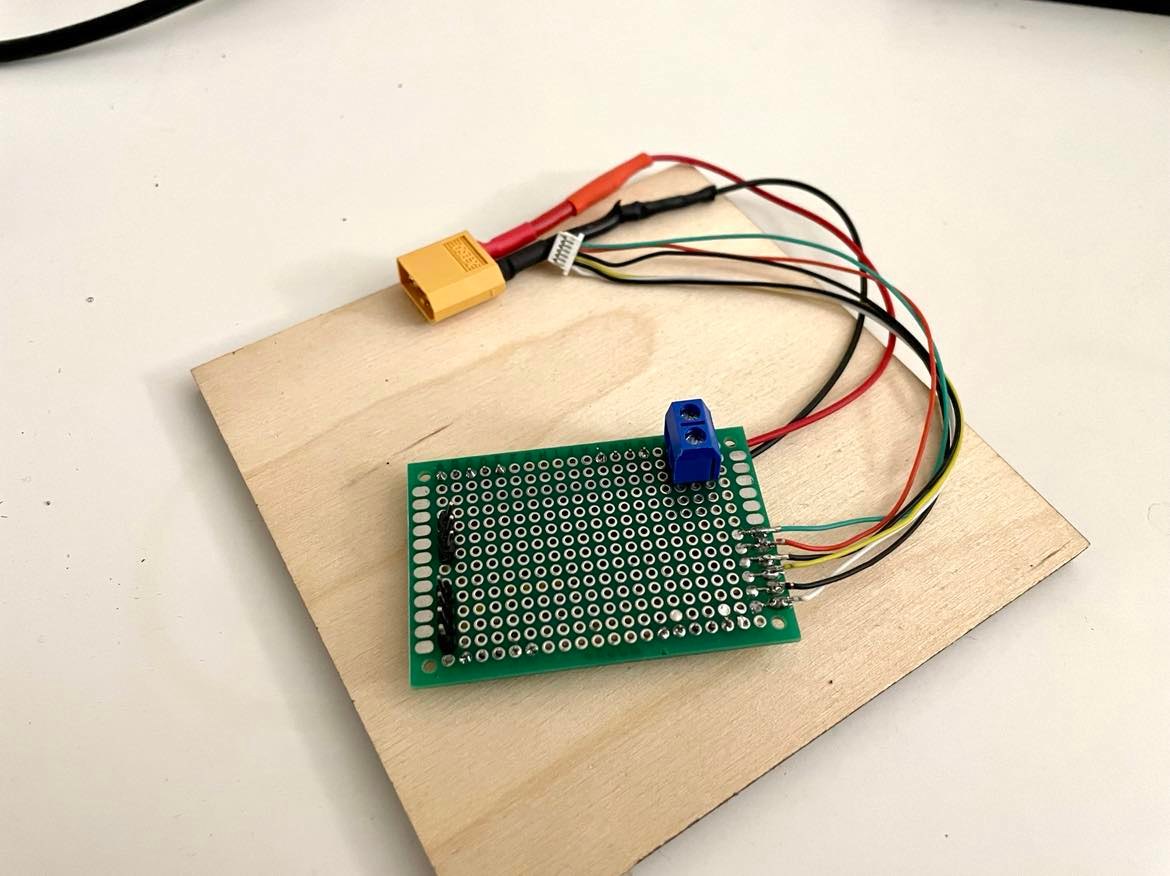
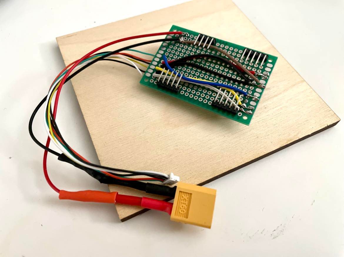
The finished PCB:
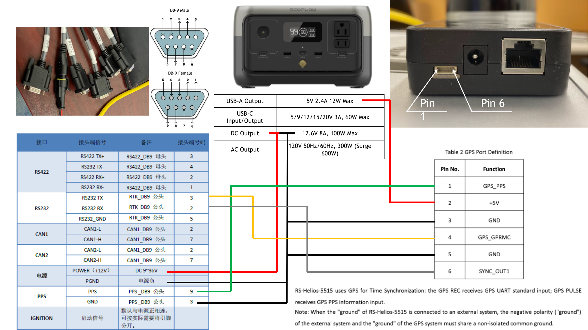
The Output wire meaning:
Color |
Meaning |
Pin Num |
|---|---|---|
White |
RS232 RX |
2 |
Yellow |
RS232 TX |
3 |
Blue |
PPS |
9 |
Black |
PPS-GND |
3 |
Black |
Power-GND |
Power black |
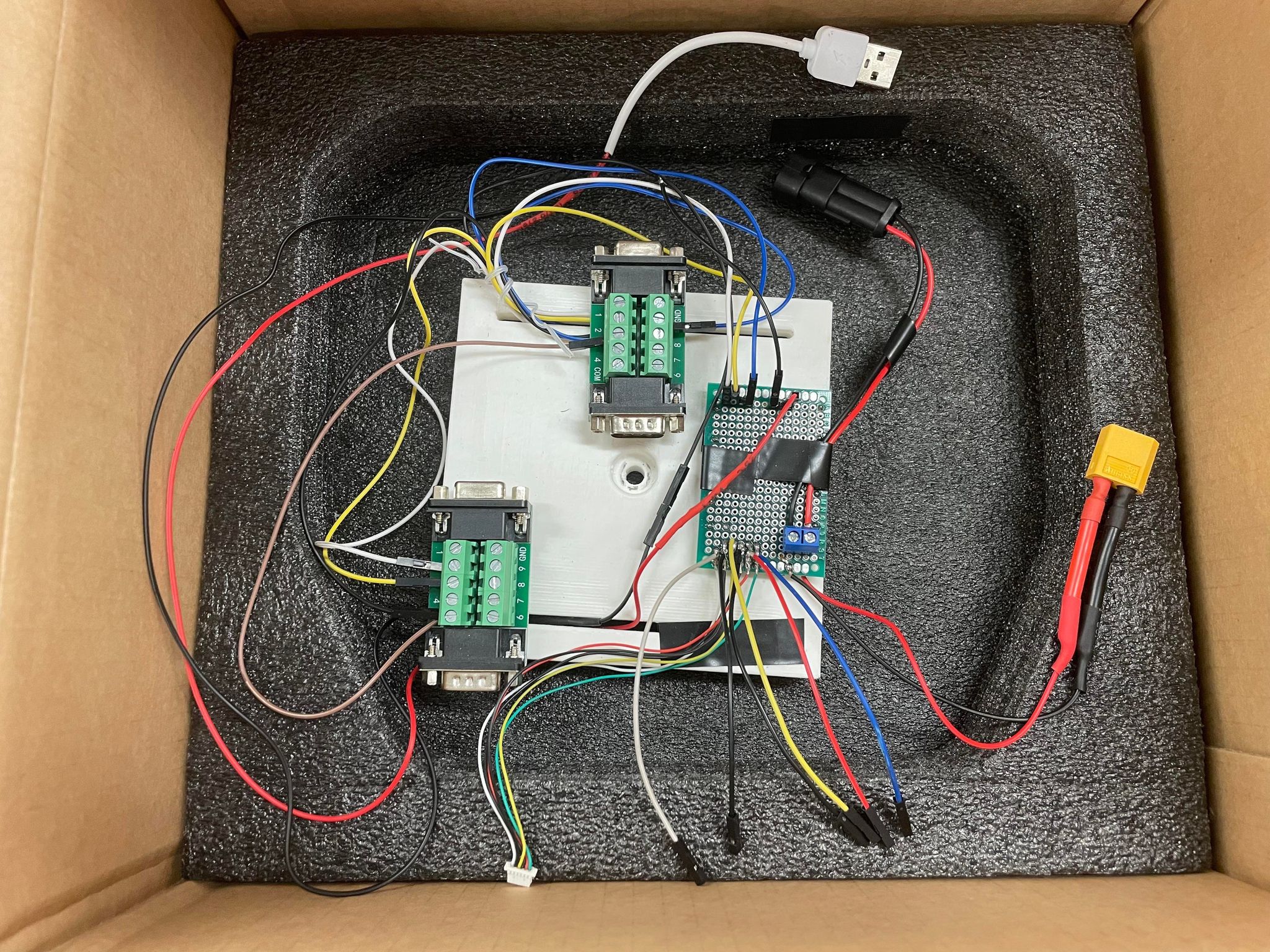
Step2: Finish the wire connection
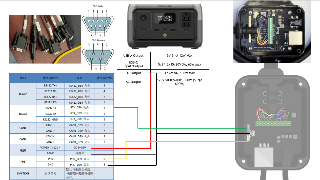
For RSLidar:
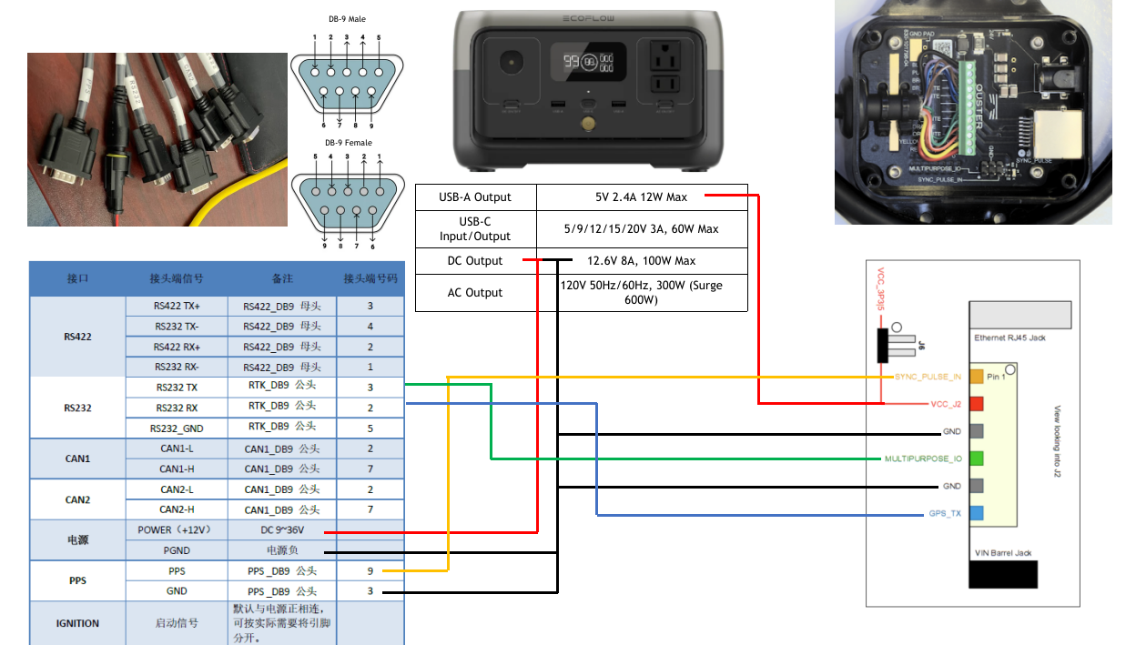
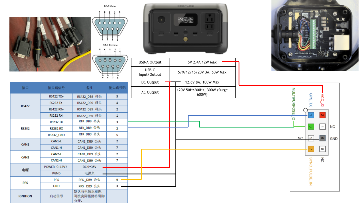
For Ouster Lidar:
There are another two different types of connection circuits: J2 and J4 (which are shown in the user manual, but these two are not ours).
This is for J2:
This is for J4:
Step3: Launch the Lidar website: 192.168.1.200
For Ouster Lidar:
Change the configuration settings as shown below:
